1/4 wave antenna
The 1/4 wave Ground plane antenna
This was the first antenna I constructed for 2 meters. It worked well for local communications and repeater work.
UHF/VHF Antenna projects

Vhf-UHF ANtenna- the J pole and super J pole
A number of years ago our ARES group had a project building 2 meter twin lead j-poles. I thought this was a neat little project.
Of course you know that if something works like this someone has to find a way to improve it. In the Old ARRL Manual i have somewhere I found the plans for a Super J Pole antenna. It was originally designed for mobile/maritime vhf communications.
At that time I found two versions: a coil wound and a semicircular 1/2 wave section inserted roughly in the middle of the antenna. Also At that time my patience (or lack there of) for winding coils neatly just didn't exist.
But I did have a piece of left over of metal brakeline from my brake job I did on my pickup. It just happened to be about 42" long. I did have a bunch of CB 1/4 wave stainless steel antennas that I had gotten a deal on - something like buy one get four. I did have a 22 inch piece of 1/4 inch rod from another project. Since I had been making and breaking fiberglass flyrods (the 1992 Aerostar hatch and my inattention certainly made custom rod building a new hobby. :-)
The only piece I needed was a piece of fiberglass about 2 inches long. A trip to the hardware store for a fiberglass electric fence pole and the project supply list was nearly complete. Two threaded 1/4 inch diameter 1 1/2 inch long spacers and two 1/4 inch cable clamps also came home.
First you cut the CB 1/4 wave antenna so the top section is a 1/2 wave length for the frequency you will be using, The bottom section is trimmed to a 3/4 wavelength. I threaded the top of bottom section of the stainless steel whip to accept the 1 1/2 inch long the 1/4-20 spacer. Next I drilled a hole in the side of each of the spacers so that I could thread a 1 1/2 inch #6 fine thread screw through the spacer into the end of the brakeline. (Please see construction Note below before proceeding to save yourself time.)
Next I cut the brake line to a 1/2 wavelength, threaded the inside of the tube to accept the #6 fine thread screw. The tubing was bent in the middle to form a tight 2 inch U turn. Next using a gallon paint bucket I rolled this U formed tubing partially around it. I must admit this manufacturing process was to say the least ..crude ..but effective.
The fiberglass electric fence pole was cut to approximately 3 inches, then sanded on the ends to fit the 1-1/2 inch 1/4 inch spacers.
The 1/4 inch rod was cut for a 1/4 wave on 146 Mhz. four holes were drilled into a 4" long section of 1 inch angle iron. Two for the mounting u-bolt and two for the antenna. The hole for the 1/4 wave rod was drillled and tapped 1/4-20. The other hole was drilled and tapped to accept the base of the formerly known as CB antenna.
The 1/4 wave stub was screwed into the angle iron base and soldered.
The main part of the Super J was assembled as follows:
1. insert bottom 3/4 wave section into the 1-1/2 in 1/4-20 spacer.
2. Insert the fiberglass piece into the other end of this same spacer.
3. install second spacer over the end of the fiberglass.
4. insert the #6 finethread screws into both spacers but don't tighten yet..
5 Insert top 1/2 wave section into the other end of the spacer.
Construction Note: I discovered I needed another tapped and drilled hole for a #6 3/8" screw to tighten the top section. So this was done as well.
6. Placing the semicircular U section up to the spacers and fiberglass section, screw this section into position. Now tighten all the screws in the spacers.
I soldered these connections more to keep the elements (rain/snow/ice) out of the joint.
7. I next sued the epoxy I had been using on my broken fishing poles to cover the bottom half of the top spacer, the 2 inch exposed section of the fiberglass and the top half of the bottom spacer.. This covered the screws going into the semi circular middle section as well..
Once the epoxy was dry on this section, this assembled unit was added to the angle Iron next to the 1/4 wave stub. The antenna was mounted on a short pole in the yard.
With my trusty MFJ 259, some coax with a PL259 on one end and stripped away center and shield on the other, and two cable clamps, I tuned the antenna to roughly 146.420. This was the local simplex frequency for my immediate area from Rumford, Peru, Sumner, Hartford and sometimes Buckfield. (You may pick any frequency you would like in the 2m band that you are using.)
For 15 years this antenna has either served as a packet primary, backup FM voice and even saw 2M sideband contacts. It gave me about 6dB over my 1/4 wave ground plane antenna it replaced.
This antenna has a low angle of takeoff.. If you live in hilly terrain it will be problematic. It works well the higher to the top of the hill or on a body of water like a pond., lake or ocean.
This was my second individual antenna construction project and definitely a learning process. It was a good learning project and suprisingly today after stting for the last 5 years sitting unused with some new clamps and feedline and TLC, it will still work.
Durability notes: Using Stainless steel and non rusting components is always better ;-).
For more construction tips and design Please visit KB0YKI website http://users.marktwain.net/aschmitz/home.html
For the Super J :http://users.marktwain.net/aschmitz/hints.html
.He also features a calculator at : http://users.marktwain.net/aschmitz/antennas/jpolecalc.html.
Also... the ARRL Handbook is where I found this design.
Good Luck and Happy building!
Wayne N1YIS
Additional resources:
A detailed description of the various middle 'phasing' elements:
https://www.hamradio.me/antennas/improving-the-super-j.html
For a three element UHF super J pole.:
https://vk6ysf.com/superjpole.htm
(Pictures in a bit)
Ringos and verticals
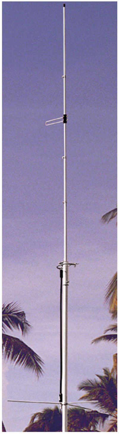
220 Ringo ranger Vert,Monoband,Indep 1-1/4m,7,Ringo II📷 ARX-220B
ARX-220B
Vert,Monoband,Indep 1-1/4m,7,Ringo II
 Cl
Cl
This antenna was
used from 2010 to 2016 with my 220Mhz radios.
https://ameritron.cushcraftamateur.com/Product.php?productid=ARX-220B